Where the cone head sits
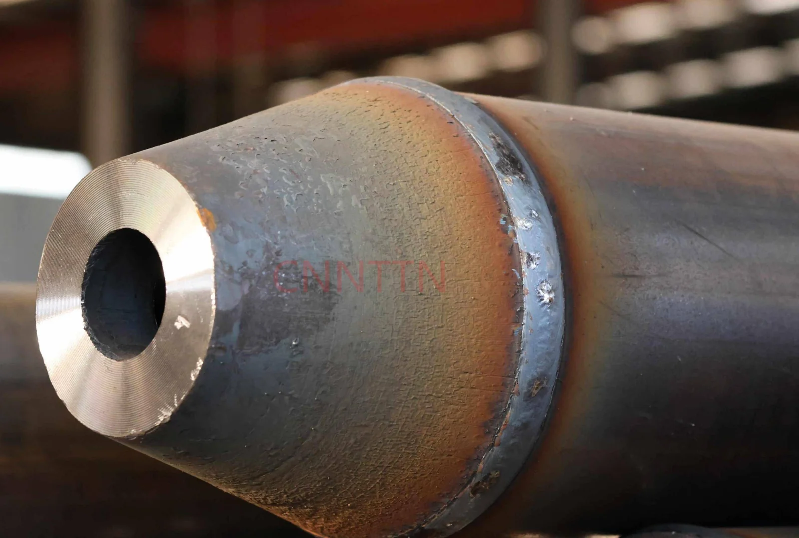
A cone head is a tapered end component used in some tubular space-frame member assemblies. It provides an interface between the tube and the connection hardware. Not every member uses the same end arrangement: flat end components and other details may be specified for different systems or positions.
The selected image shows a tapered component connected to a steel tube. It illustrates appearance and location only; it does not establish an approved design detail or weld requirement.
Treat the end as part of an assembly
The relevant information is not just the cone's outside size. Ask how the end component relates to the tube size, fastener, sleeve, node geometry and finished member length. These details should be consistent across the approved drawings and parts list.
Do not assume that a cone head with a similar profile can be substituted into another manufacturer's system. Compatibility and capacity require confirmation within the actual connection design.
Questions before fabrication
A useful technical enquiry should identify the assembly drawing and revision, required materials, member identification and the agreed inspection requirements. Where welding is specified, obtain the applicable welding documentation and acceptance basis rather than extracting a weld size from a photograph.
The fabrication review can also ask how orientation is controlled, how completed member dimensions are checked and how any nonconforming components are isolated and recorded. These are coordination questions; the project specification must provide the actual criteria.
Coating and handling interfaces
End components often need to pass through several workshop stages before delivery. Ask which surfaces must remain suitable for assembly, how component markings are preserved, and how finished members will be protected during handling. A finish selected for appearance alone may not address the project's exposure and assembly requirements.
The approved system instructions should govern treatment of contact areas and threaded parts. This article does not prescribe a coating thickness or a workshop repair procedure.
Information to keep with the delivered member
Link the member mark to its drawing revision and associated inspection records. Packing information should let the installation team identify the correct components without relying solely on visual comparison.
When dimensions or site conditions differ from the approved information, use the agreed clarification process. Avoid field cutting, welding or substituting connection parts without the required engineering approval.
Continue with fabrication and quality records for a broader document-led workflow. General fabrication background is available from the Steel Construction Institute and BCSA.
References & further reading
Background resources; applicability and current editions must be checked for the project. Referenced organisations do not endorse this site.